Cilium Network Topology and Traffic Path on AWS
This post explores the network topology and traffic path between two cross-host Pods in a Cilium powered K8S cluster on AWS. We will use general Linux commands to fulfill this task. At the end of this post, we will get a picture like this:
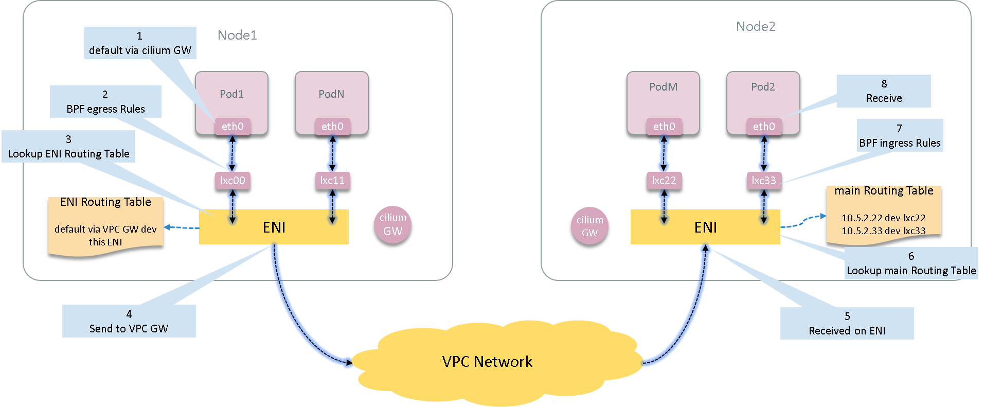
Besides, we’ll also look into the code to see how Cilium achieve this.
Code based on v1.10.7.
Also, the network topology and routing rules/entries are quite similar in other cloud vendors, such as Cilium on AlibabaCloud.
This post is included in Cilium Code Walk Through Series.
- 1 Preparation
- 2 Egress: Pod -> Host -> VPC Network
- 3 Ingress
- 4 The implementation: code walk through
- 5 Summary
- References
1 Preparation
1.1 Test Environment
We have two K8S hosts:
- node1:
10.5.2.48 - node2:
10.5.2.58
and two Pods:
- pod1
10.5.2.11on node1 - pod2
10.5.2.22on node2
Nodes and pods are in the same VPC, with VPC gateway 10.5.2.1.
Note: For security reasons, as well as easy of understanding, I have substituted the real IP/MAC addresses with faked ones. This should not undermine the meaningfulness of this post.
1.2 Container netns and nsenter
We will use nsenter tool tool to execute commands in container’s network
namespace on host, the format is:
$ nsenter -t <pid> -n <command>
where,
-t <pid>: the target process<pid>-n: enter network namespace<command>: command to execute
this is equivalent to docker exec <container> <command>, but more flexible
than the latter, as there are often shortage of network tools or lack of
privileges inside containers, executing commands on hosts doesn’t have this
limitation.
Get container process ID:
root@node1 # docker inspect 04d740a33726 | grep Pid
            "Pid": 75869,
75869 is just the pid we wanted.
1.3 Verify Basic Connectivity
Ping pod2 from pod1, make ensure it is reachable:
root@node1 # nsenter -t 75869 -n ping 10.5.2.22 -c 2
64 bytes from 10.5.2.22: icmp_seq=1 ttl=61 time=0.248 ms
64 bytes from 10.5.2.22: icmp_seq=2 ttl=61 time=0.208 ms
OK! Next, we will explore the exact path of these packets, namely the network devices, routing table, arp tables, BPF hooks all the way.
2 Egress: Pod -> Host -> VPC Network
2.1 Network inside container
Start our journey from pod1. Check the network devices inside pod1:
root@node1 # nsenter -t 75869 -n ip a
1: lo: <LOOPBACK,UP,LOWER_UP> mtu 65536 qdisc noqueue state UNKNOWN qlen 1000
    ...
42: eth0@if43: <BROADCAST,MULTICAST,UP,LOWER_UP> mtu 9001 qdisc noqueue state UP
    link/ether ee:14:d3:9a:62:42 brd ff:ff:ff:ff:ff:ff link-netnsid 0
    inet 10.5.2.11/32 brd 10.5.2.11 scope global eth0
As can be seen, it has a loopbak interface lo and a network interface eth0
with IP address 10.5.2.11.
Pay attention to 42: eth0@if43, this special notation means that eth0 has an
ifindex numbered 42, and that the devices with ifindex 42 and 43
compose a veth pair. This ifindex is unique within the host (node1 in
this case), we will see this again later.
Next, check the route table inside container:
root@node1 # nsenter -t 75869 -n route -n
Kernel IP routing table
Destination     Gateway         Genmask         Flags Metric Ref    Use Iface
0.0.0.0         10.5.2.191   0.0.0.0         UG    0      0        0 eth0
10.5.1.191   0.0.0.0         255.255.255.255 UH    0      0        0 eth0
It can be seen that the gateway for this pod is 10.5.1.191, and all egress
traffic will forward to this gateway. Look for the gateway on host:
root@node1 # ip a | grep 10.5.2.191 -B 2
31: cilium_host@cilium_net: <...> mtu 9001 ... qlen 1000
    link/ether 0a:ee:d6:5f:6c:32 brd ff:ff:ff:ff:ff:ff
    inet 10.5.2.191/32 scope link cilium_host
We can see that the container gateway is held by device cilium_host. Actually
cilium_host and cilium_net compose another veth pair, they are both on the
host network space, and will be created on cilium-agent start.
Next, check the ARP table inside container:
root@node1 # nsenter -t 75869 -n arp -n
Address                  HWtype  HWaddress           Flags Mask            Iface
10.5.2.191            ether   86:05:d4:99:a9:f5   C                     eth0
10.5.2.48             ether   86:05:d4:99:a9:f5   C                     eth0
It can be seen that both container’s gateway and host IP point to the same MAC
address 86:05:d4:99:a9:f5. Let further determine which device holds this
address.
2.2 Veth Pair connecting to host
root@node1 # ip link | grep 86:05:d4:99:a9:f5 -B 1
43: lxc050ba70e11a8@if42: <BROADCAST,MULTICAST,UP,LOWER_UP> mtu 9001 qdisc ... qlen 1000
    link/ether 86:05:d4:99:a9:f5 brd ff:ff:ff:ff:ff:ff link-netnsid 1
That’s it! Device lxc050ba70e11a8 holds it. Notice the 43:
lxc050ba70e11a8@if42 notation, and recall that container’s eth0 actually
holds ifindex=42, so we are now ensure that:
- pod1 connects to host via veth pair (
if42 <--> if43, or in name presentationeth0 <--> lxc050ba70e11a8) - default gateway in pod points to the
cilium_hostdevice on host - next L3 hop of the Pod generated traffic is
cilium_host - next L2 hop of the Pod generated traffic is the host end of the veth pair (
lxc050ba70e11a8)
This is exactly how pod egress traffic flows from container to host.
2.3 Egress BPF Code
One of Cilium’s great powers is the dynamic traffic manipulation. It implements this by utilizing BPF. Detailed explanations on this topic is beyong the scope of this post, refer to the official doc BPF and XDP Reference Guide if you are interested (or my TRANSLATION if you could read Chinese).
Cilium uses tc BPF to filter ingress and egress traffic for containers. Let’s
see the egress part:
root@node1:~  # tc filter show dev lxc050ba70e11a8 egress
filter protocol all pref 1 bpf
filter protocol all pref 1 bpf handle 0x1 bpf_lxc.o:[from-container] direct-action not_in_hw tag db59e2ea8177ded3
Note: if the output of the above command doesn’t show the
bpf_lxc.o:[from-container] direct-action not_in_hw tag db59e2ea8177ded3info, it may be that youriproute2package is too old, try to upgrade to a newer version.
List all loaded BPF programs on this host (node1):
root@node1:~  # bpftool prog
288: sched_cls  tag a390cb0eda39ede9
        loaded_at Oct 22/10:48  uid 0
        xlated 808B  jited 637B  memlock 4096B  map_ids 182,169
...
294: sched_cls  tag 596c1921e0319e72
        loaded_at Oct 22/10:48  uid 0
        xlated 176B  jited 157B  memlock 4096B
297: sched_cls  tag db59e2ea8177ded3
        loaded_at Oct 22/10:48  uid 0
        xlated 19144B  jited 11706B  memlock 20480B  map_ids 285,169,171,286,287,172,277,183,283,173,179,167,180
Let’s dig further to see what the BPF code/rules looks like. Dump the interpreted BPF code:
root@node1:~  # bpftool prog dump xlated id 297
   0: (bf) r6 = r1
   1: (b7) r7 = 0
   2: (63) *(u32 *)(r6 +60) = r7
   3: (63) *(u32 *)(r6 +56) = r7
   4: (63) *(u32 *)(r6 +52) = r7
   5: (63) *(u32 *)(r6 +48) = r7
   6: (63) *(u32 *)(r6 +64) = r7
   7: (18) r2 = 0xffffff5a
   9: (79) r1 = *(u64 *)(r6 +80)
  10: (79) r8 = *(u64 *)(r6 +216)
   ...
Dump the JITed BPF code:
root@node1:~  # bpftool prog dump jited id 297
   0:   push   %rbp
   1:   mov    %rsp,%rbp
   4:   sub    $0x228,%rsp
   b:   sub    $0x28,%rbp
   f:   mov    %rbx,0x0(%rbp)
  13:   mov    %r13,0x8(%rbp)
  17:   mov    %r14,0x10(%rbp)
  1b:   mov    %r15,0x18(%rbp)
  1f:   xor    %eax,%eax
  21:   mov    %rax,0x20(%rbp)
  ...
OK, no further digging. If the egress traffic was not dropped by the BPF code/rules, it will arrive the host, which will be processed by host routing facilities.
2.4 Host routing table
Look at the host routing table:
root@node1:~  # ip rule list
9:      from all fwmark 0x200/0xf00 lookup 2004
100:    from all lookup local
32766:  from all lookup main
32767:  from all lookup default
We see that there are 4 routing tables: 2004, local, main, default.
Check what’s in each:
root@node1:~  # ip route show table 2004
local default dev lo scope host

root@node1 $ ip route show table main
default via 10.5.2.1 dev eth0
10.5.2.0/24 dev eth0 proto kernel scope link src 10.5.2.48
The egress traffic from Pod1 will hit the main table.
Note: To be more specific, Pod IP is allocated from ENI, and each ENI has its own routing table for egress traffic. In my case here, Pod1’s IP comes from node1’s default ENI (eth0), thus the traffic will hit the
maintable. If you have multiple ENIs, the routing should be a little different here.
The main routing table is also node1’s default routing table (dont’ be misled
by the default table above, it’s just a table with name default, but not the
default table for host).
The default gateway of node1 is 10.5.2.1 (the VPC gateway). So the egress
traffic of pod1 will eventually be sent to VPC gateway.
This completes the egress part of our traffic journey.
3 Ingress
If VPC network correctly routes the traffic to Node2 (vendor’s responsibility), then those packets will arrive at Node2’s corresponding ENI. Let’s see what will be done for those packets.
3.1 Host routing table
root@node2:~  # ip rule list
9:      from all fwmark 0x200/0xf00 lookup 2004
100:    from all lookup local
32766:  from all lookup main
32767:  from all lookup default
root@node2:~  # ip route show table 2004
local default dev lo scope host

node2 $ ip route show table main
default via 10.5.1.1 dev eth0
10.5.2.22 dev lxcd86fc95bf974 scope link
...
As can be seen, there is a decicated route for Pod2:
10.5.2.22 dev lxcd86fc95bf974 scope link
This means that all traffic destinated for 10.5.2.22 will be forwarded to
lxcd86fc95bf974.
3.2 Ingress BPF code
Cilium will inject ingress BPF rules for each of the lxcxx devices it created.
Let’s check this one:
root@node2:~  # tc filter show dev lxcd86fc95bf974 ingress
filter protocol all pref 1 bpf
filter protocol all pref 1 bpf handle 0x1 bpf_lxc.o:[from-container] direct-action not_in_hw tag c17fab4b3f874a54
If you are interested in the exact BPF code, following step are much the same as our previous egress part:
root@node2:~  # bpftool prog
156: sched_cls  tag a390cb0eda39ede9
        loaded_at Oct 22/10:59  uid 0
        xlated 808B  jited 637B  memlock 4096B  map_ids 46,33
...
165: sched_cls  tag c17fab4b3f874a54
        loaded_at Oct 22/10:59  uid 0
        xlated 19144B  jited 11706B  memlock 20480B  map_ids 155,33,35,156,157,36,147,47,153,37,43,31,44

root@node2:~  # bpftool prog dump xlated id 165 | head -n 10
   0: (bf) r6 = r1
   1: (b7) r7 = 0
   2: (63) *(u32 *)(r6 +60) = r7
   3: (63) *(u32 *)(r6 +56) = r7
   4: (63) *(u32 *)(r6 +52) = r7
   5: (63) *(u32 *)(r6 +48) = r7
   6: (63) *(u32 *)(r6 +64) = r7
   7: (18) r2 = 0xffffff5a
   9: (79) r1 = *(u64 *)(r6 +80)
  10: (79) r8 = *(u64 *)(r6 +216)
3.4 Container receive
If the traffic is not dropped by Cilium network policy rules (ingress BPF), then
the packets will go through the host side veth pair and eventually arrive at the
eth0 inside container - the final destination of our journey.
Now re-depict the global data flow picture here:
4 The implementation: code walk through
// Call stack of cilium-cni
interfaceAdd               // plugins/cilium-cni/interface.go
 |-routingInfo.Configure() // pkg/datapath/linux/routing/routing.go
                |-route.ReplaceRule("from all to 10.5.2.22 lookup main") // INGRESS rule: outside -> pod
                |
                |-route.ReplaceRule("from 10.5.2.22 lookup <tableId>")   // EGRESS  rule: pod -> outside
                |-netlink.RouteReplace("default via <vpc gw> dev <eni>") // EGRESS route entry 1: pod -> outside
                |-netlink.RouteReplace("<vpc gw> dev <eni> scope link")  // EGRESS route entry 2: pod -> outside

// Call stack of cilium-agent
reloadDatapath             // pkg/datapath/loader/loader.go
  |-if ep.RequireEndpointRoute()
      upsertEndpointRoute(ep, *ip.IPNet(32))                              // INGRESS route entry: outside -> pod
See our Cilium Code Walk Through Series for more detailed call stacks of cilium-agent and cilium-cni.
The below table summarizes the rules, route entries, and by whom they are set:
| Direction | Resource | Owner (set by whom) | Command to inspect |
|---|---|---|---|
| Ingress | routing rule | cilium-cni (/opt/cni/bin/cilium-cni) |
ip rule list |
| Ingress | routing entry | cilium-agent |
ip route show table <table> |
| Egress | routing rule | cilium-cni (/opt/cni/bin/cilium-cni) |
ip rule list |
| Egress | routing entry | cilium-cni (/opt/cni/bin/cilium-cni) |
ip route show table <table> |
4.1 Pod ingress rule & route entry
The rule for all traffic ingressing to a pod/endpoint
is set by Cilium CNI plugin cilium-cni during
pod network creation (refer to the above calling stack).
The resulted rule:
(node2) $ ip rule
20:     from all to 10.5.2.22 lookup main  # outside -> container, lookup main
and the routing entry:
node2 $ ip route show table main
10.5.2.22 dev lxcd86fc95bf974 scope link
...
But note that, different from the policy routint rule, the route entry is set by
cilium-agent during endpoint creating process, and,
--enable-endpoint-routes=true need to be configured for the agent, which defaults to false.
4.2 Pod egress rule & route entry
For the egress direction, both the routing rule and routing entries are set by cilium-cni, with something
looks like below:
$ ip rule
111:    from 10.5.2.22 lookup 11           # container -> outside, lookup table 11
$ ip route show table 11
default via 10.5.2.1 dev eni2              # default via VPC gateway
10.5.2.1 dev eni2 scope link
5 Summary
This post explores the network topology and data flow of the inter-host traffic between two pods in a Cilium-powered K8S cluster on AWS. We used common Linux command line tools to fulfill this task. We also walked through the code a little. Hope these contents are helpful to you!