Traffic Mirroring: Theory and Practice (with tc and Tunneling)
- 1 Theory
- 2 Practice: tc + VxLAN
- 3 Remarks
- References
- Appendix: Topology discovery of docker
bridgenetwork
Traffic mirroring (also called port mirroring in some cases) is a technique to send a copy of the network traffic to a backend system. It is commonly used by network developers and administrators/operators to monitor network traffic or diagnose problems. Many systems rely on traffic mirroring function, such as intrusion detection system (IDS), passive probe, real user monitoring (RUM), traffic replay system, etc. [1]
Traditional traffic mirroring solutions are based on hardware switches, and are vendor-specific, which often found to be expensive, hard to use and difficult to evolve. With the raising of network virtualization techniques, software-based and vendor-agnostic solutions emerge, which are more flexible and easier to upgrade.
This post first discusses the technical requirements for traffic mirroring, then
investigates a specific solution based on tc and tunneling. To make this a
hands-on guide, we will set up a container-based virtual environment,
but it also fits the physical (servers and networks) environments.
1 Theory
1.1 Technical requirements
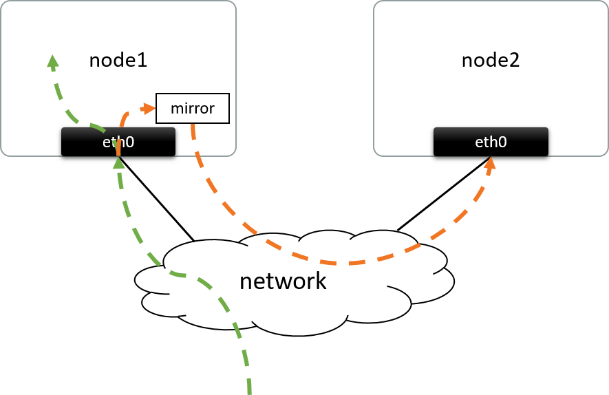
Fig 1.1. Mirroring the ingress traffic of eth0@node1 to a remote node
Traffic mirroring involves making a copy of some specific traffic, and sending that copy to a destination place for further processing. The destination place could be one of a:
- network device: e.g. a physical NIC/port directly connected via cable
- remote node: usually connected via network, as shown in the above.
Fig 1.1 performs mirroring merely on the ingress packets, but the egress could also be mirrored; besides, you could also filter the packets (e.g. select TCP SYN packets only) before copying them.
Another thing needs to concern: should we copy each interested packet exactly as it is, or just part of it? Well, this depends on your needs, such as,
- If intended to analyze L7 message contents, e.g. HTTP requests, you need to copy the intact packet,
- If intended to analyze L4 flow events, e.g. TCP flow stats, you could just keep L2-L4 headers and drop the remaining bytes to save bandwidth and storage space,
- If intended to analyze L2 flow events, then maybe only L2 header needs to be preserved to further reduce bandwidth and storage.
1.2 Solutions
With the above requirements in mind, let’s break them down and try to propose a solution.
Capture, filter and copy packets
This is the first problem we need to solve. Actually, it depends on the networking infrastructures we are running on. Such as,
- With OVS stack: port mirroring function may be used, see Traffic Mirroring with OVS as an example;
- With kernel stack: tools like
tcmay be suitable; - If none of the existing tools works for you, you may end up with writing your own mirroring stuffs based on libraries such as libpcap.
Send copied packets to the destination
This is what we care about more in this post. If mirrored packets already at hand, how should we correctly send them to the remote node?
Challenges
Put mirrored packets directly on the wire and send out won't work, as both the
dsc_mac and dst_ip of the packets are destined to the local node rather than
remote node, which results to,
- Switches will not forward them to the remote node; even worse, they may forward them back to local node which leads to a loop;
- Even if you struggled to make those packets arrived to the destination node (e.g. via direct cables), they may still get dropped before arriving to the final network device. For example, the final device responsible for processing those packets is a virtual network device behind a physical NIC; in this case, the packets will get dropped at the NIC due to destination IP (and MAC) mismatch with the current NIC.
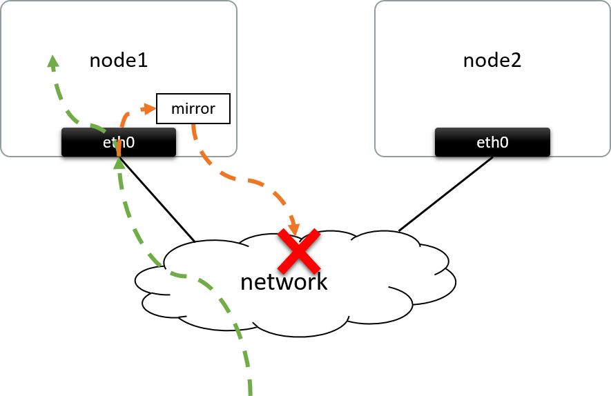
Fig 1.2. Mirrored traffic won't arrive to the destination node if directly them put on the wire
Also, you couldn’t send them there by changing the IP/MAC of mirrored packets to destination node's, as altered packets are not “mirrored packets” anymore - which will be useless to the receiving side (e.g. IDS).
Then, how could we send them to the remote node without changing them? Here comes tunneling.
Sending via tunneling
One feasible way to send the mirrored traffic to the remote node is: treat each copied packet as an opaque payload, encapsulate it into another packet and send to the remote node; at the receiving side, extract this mirrored packet by decapsulating the outer header.
There are many encapsulation formats to achieve this purpose, such as VxLAN, which puts the original packet into a new UDP packet, as shown below:
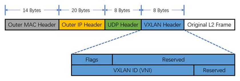
Fig 1.3. VxLAN header, with the "Original L2 Frame" field stores a mirrored packet. Image from @ethansmithron
1.3 A specific solution: tc + VxLAN
With all the above analysis, we are now ready to implement a sample traffic mirroring system.
And of course, we won’t make everything from scratch: Linux already provides us lots of tools that could be used to fulfill this task, including:
tc: capture and filter trafficVxLAN: encapsulate mirrored packets
2 Practice: tc + VxLAN
2.1 Set up playground
Let’s setup our container based playground.
2.1.1 Prerequisites
Make sure docker is installed before proceeding on. And this post uses docker’s default settings, which indicates,
- There will be a Linux bridge
docker0created on the host, docker0servers as the gateway of the default docker network10.0.108.0/23(configured in/etc/docker/daemon.json)- When starting a container with
docker runwith no special networking parameters specified, it will allocate an IP address from10.0.108.0/23, and attached the container todocker0bridge with a veth pair. We will see this in the following.
Now, we’re ready to march on.
2.1.2 Create two containers
$ docker run -d --name ctn-1 alpine:3.11.6 sleep 60d
$ docker run -d --name ctn-2 alpine:3.11.6 sleep 60d
$ docker ps | grep ctn
f0322e340e03        alpine:3.11.6  "sleep 60d"   .. ctn-2
44f9a9804e77        alpine:3.11.6  "sleep 60d"   .. ctn-1
Get container netns:
$ NETNS1=$(docker inspect --format "{{.State.Pid}}" ctn-1)
$ NETNS2=$(docker inspect --format "{{.State.Pid}}" ctn-2)
$ echo $NETNS1 $NETNS2
41243 361417
In the following, we will use nsenter -t <netns> -n <commands> to execute
commands in container’s network namespace, this is equivalent to execute those
commands inside the container.
$ nsenter -t $NETNS1 -n ip addr
1: lo: <LOOPBACK,UP,LOWER_UP> mtu 65536 ...
    inet 127.0.0.1/8 scope host lo
258: eth0@if259: <BROADCAST,MULTICAST,UP,LOWER_UP> mtu 1500 ...
    inet 10.0.108.2/23 brd 10.0.109.255 scope global eth0
$ nsenter -t $NETNS2 -n ip addr
1: lo: <LOOPBACK,UP,LOWER_UP> mtu 65536 ...
    inet 127.0.0.1/8 scope host lo
273: eth0@if274: <BROADCAST,MULTICAST,UP,LOWER_UP> mtu 1500 ...
    inet 10.0.108.3/23 brd 10.0.109.255 scope global eth0
Now the network topology:
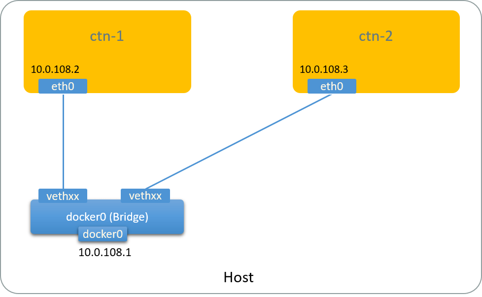
Fig 2.1. Default network topology of docker containers
See Appendix if you are curious about how this topology comes to place.
2.1.3 Connect containers with another network
Now,
- Add a new Linux bridge
docker1 - Add a new NIC to each of the container, and configure an IP for it
- Connect containers to
dockervia the new NICs.
The topology will be:
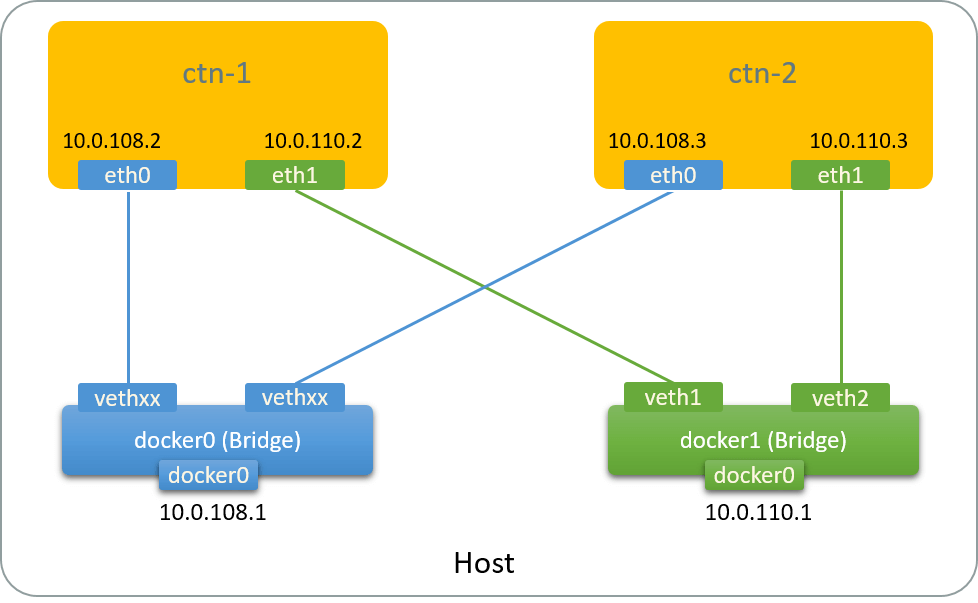
Fig 2.2. Network topology after adding a bridge and two vNICs to containers
Add bridge
$ ip link add docker1 type bridge          # Add a new Linux bridge `docker1`
$ ip addr add 10.0.110.1/24 dev docker1    # Configure management IP address for this bridge
$ ip link set docker1 up
Add NIC to ctn-1
Add a veth pair, with one end serving as vNIC for ctn-1, and the other end
attaching to docker:
$ ip link add veth1 type veth peer name peer1              # Add veth pair
$ ip link set peer1 netns $NETNS1                          # Move one end to container's netns

$ nsenter -t $NETNS1 -n ip link set peer1 name eth1        # Rename it to eth1
$ nsenter -t $NETNS1 -n ip addr add 10.0.110.2/23 dev eth1 # Configure IP address
$ nsenter -t $NETNS1 -n ip link set eth1 up

$ ip link set veth1 master docker1                         # Attach the host side to bridge docker1
$ ip link set veth1 up
Add NIC to ctn-2
Same for ctn-2:
$ ip link add veth2 type veth peer name peer2
$ ip link set peer2 netns $NETNS2

$ nsenter -t $NETNS2 -n ip link set peer2 name eth1
$ nsenter -t $NETNS2 -n ip addr add 10.0.110.3/23 dev eth1
$ nsenter -t $NETNS2 -n ip link set eth1 up

$ ip link set veth1 master docker1
$ ip link set veth2 up
2.1.4 Test reachability
First, take a look at the routing table inside ctn-1:
$ nsenter -t $NETNS1 -n ip route
default via 10.0.108.1 dev eth0
10.0.108.0/23 dev eth0 proto kernel scope link src 10.0.108.2
10.0.110.0/23 dev eth1 proto kernel scope link src 10.0.110.2
The last route entry says that network 10.0.110.0/23 (docker1) is reachable
via eth1. Verify it:
$ nsenter -t $NETNS1 -n ping 10.0.110.3
64 bytes from 10.0.110.3: icmp_seq=1 ttl=64 time=0.053 ms
^C

$ nsenter -t $NETNS1 -n ping 10.0.108.3
64 bytes from 10.0.108.3: icmp_seq=1 ttl=64 time=0.053 ms
^C
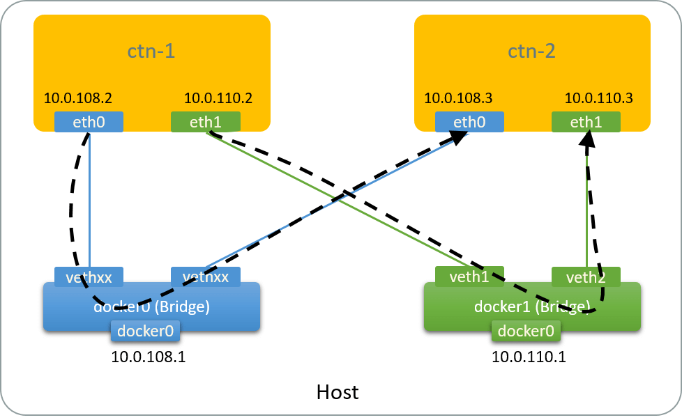
Fig 2.3. Traffic paths when pinging each IP address of ctn-2 from ctn-1
As shown in the above picture, we can now reach ctn-2 via a distinct path (via
eth1), which is independent from the default one (via eth0). We will send
our mirrored packets with this path in the next.
2.2 Set up VxLAN tunnel
Now we are ready to set up a VxLAN tunnel on top of the eth1 NICs between
ctn-1 and ctn-2 .
2.2.1 Setup VxLAN tunnel on ctn-1
$ nsenter -t $NETNS1 -n ip link add vxlan0 type vxlan id 100 local 10.0.110.2 remote 10.0.110.3 dev eth1 dstport 4789
$ nsenter -t $NETNS1 -n ip link set vxlan0 up
$ nsenter -t $NETNS1 -n ip addr
1: lo: <LOOPBACK,UP,LOWER_UP> mtu 65536 ...
258: eth0@if259: <BROADCAST,MULTICAST,UP,LOWER_UP> mtu 1500 ...
    inet 10.0.108.2/23 brd 10.0.109.255 scope global eth0
9: vxlan0: <BROADCAST,MULTICAST,UP,LOWER_UP> mtu 1450 qdisc ...
    link/ether 4e:b6:9d:1e:ac:bd brd ff:ff:ff:ff:ff:ff
277: eth1@if278: <BROADCAST,MULTICAST,UP,LOWER_UP> mtu 1500 ...
    inet 10.0.110.2/23 scope global eth1
2.2.2 Setup VxLAN tunnel on ctn-2
$ nsenter -t $NETNS2 -n ip link add vxlan0 type vxlan id 100 local 10.0.110.3 remote 10.0.110.2 dev eth1 dstport 4789
$ nsenter -t $NETNS2 -n ip link set vxlan0 up
2.2.3 Topology
Now the topo:
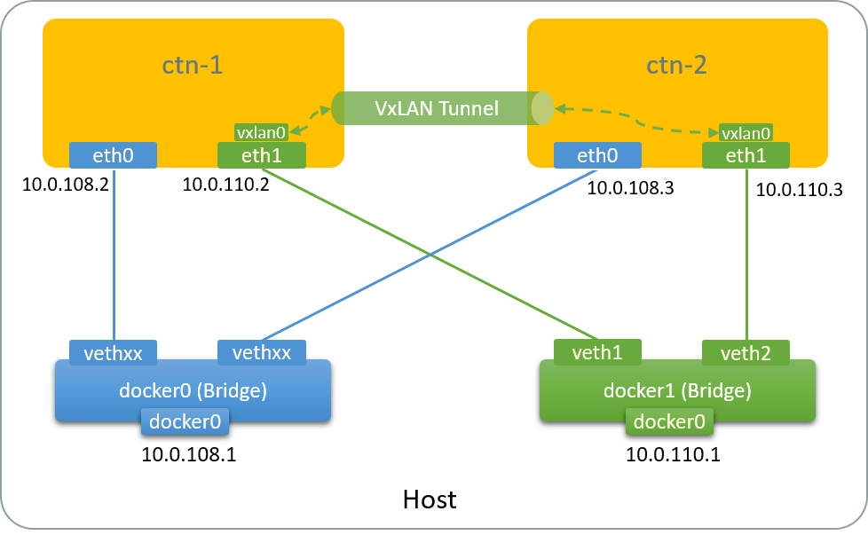
Fig 2.4. Network topology after adding a VxLAN tunnel
Traffic path between vxlan0@ctn-1 and vxlan0@ctn-2:
- The conceptual path:
vxlan0@ctn-1 -> tunnel -> vxlan0@ctn-2 - The real path:
vxlan0@ctn-1 -> eth1@ctn-1 -> veth1 -> docker1 -> veth2 -> eth1@ctn-2 -> vxlan0@ctn-2
2.3 Filter & mirror traffic with tc
The Linux kernel ships with an excellent traffic control (tc) subsystem, which
can filter and shape the bandwidth of network devices by
queuing the packets on the devices first then transmitting them by specific algorithms. These algorithms are
called qdiscs (queuing disciplines).
Qdiscs in the kernel [5]:
                Userspace programs
                     ^
                     |
     +---------------+-----------------------------------------+
     |               Y                                         |
     |    -------> IP Stack                                    |
     |   |              |                                      |
     |   |              Y                                      |
     |   |  / ----------> Forwarding ->                        |
     |   ^ /                           |                       |
     |   |                             |                       |
     |   ^                             Y          /-qdisc1-\   |
     |   |                            Egress     /--qdisc2--\  |
  --->->Ingress                       Classifier ---qdisc3---- | ->
     |   Qdisc                                   \__qdisc4__/  |
     |                                            \-qdiscN_/   |
     +----------------------------------------------------------+
     Fig 2.5. tc qdisc in the kernel, credit to Jamal Hadi Salim [5]
It needs to be noted that, traffic shaping only works on the egress side - as you can only control the transmitting behavior of yourself - ingress bandwidth is determined by other nodes, which are out of our control for most of the time. But the good news is, there is still a qdisc for ingress, which is used for filtering (and dropping if you like) the ingress packets, as shown in the above picture.
For more information on Linux’s traffic control subsystem, refer to [5,2] and this translation if you can read Chinese.
For simplicity, we’ll only mirror the ingress packets in the next.
2.3.1 Add the ingress qdisc
Add a qdisc in eth0@ctn-1’s ingress path:
$ nsenter -t $NETNS1 -n tc qdisc add dev eth0 handle ffff: ingress
$ nsenter -t $NETNS1 -n tc -s qdisc ls dev eth0
qdisc noqueue 0: root refcnt 2
 Sent 0 bytes 0 pkt (dropped 0, overlimits 0 requeues 0)
 backlog 0b 0p requeues 0
qdisc ingress ffff: parent ffff:fff1 ----------------
 Sent 4284 bytes 68 pkt (dropped 0, overlimits 0 requeues 0)
 backlog 0b 0p requeues 0
All ingress packets on eth0 will be sent to this qdisc.
2.3.2 Add a packet filter to qdisc
Add a filter to choose what types of packets to mirror:
# match all packets, mirrored to vxlan0 device
$ nsenter -t $NETNS1 -n tc filter add dev eth0 parent ffff: protocol all u32 match u32 0 0 action mirred egress mirror dev vxlan0
Check the filter:
# -s: show statistics
# -p: pretty format output for filter info
$ nsenter -t $NETNS1 -n tc -s -p filter ls dev eth0 parent ffff:
filter protocol ip pref 49152 u32
filter protocol ip pref 49152 u32 fh 800: ht divisor 1
filter protocol ip pref 49152 u32 fh 800::800 order 2048 key ht 800 bkt 0 terminal flowid ??? not_in_hw  (rule hit 0 success 0)
  match IP protocol 1 (success 0 )
        action order 1: mirred (Egress Mirror to device vxlan0) pipe
        index 1 ref 1 bind 1 installed 18 sec used 18 sec
        Action statistics:
        Sent 0 bytes 0 pkt (dropped 0, overlimits 0 requeues 0)
        backlog 0b 0p requeues 0
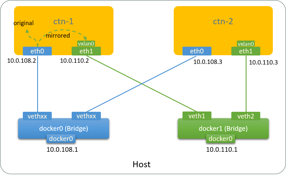
Fig 2.6. Network topology after adding tc qdisc & filter
2.3.3 Generate traffic and test mirroring
Generate test traffic: ping eth0@ctn-1 from host,
$ ping 10.0.108.2
PING 10.0.108.2 (10.0.108.2) 56(84) bytes of data.
64 bytes from 10.0.108.2: icmp_seq=1 ttl=64 time=0.063 ms
64 bytes from 10.0.108.2: icmp_seq=2 ttl=64 time=0.053 ms
...
Capture the traffic at eth1@ctn-2:
$ nsenter -t $NETNS2 -n tcpdump -nn -i eth1
19:03:20.767998 IP 10.0.110.2.35710 > 10.0.110.3.4789: VXLAN, flags [I] (0x08), vni 100
IP 10.0.108.1 > 10.0.108.2: ICMP echo request, id 30513, seq 1, length 64

19:03:21.767482 IP 10.0.110.2.35710 > 10.0.110.3.4789: VXLAN, flags [I] (0x08), vni 100
IP 10.0.108.1 > 10.0.108.2: ICMP echo request, id 30513, seq 2, length 64
As the output shows, the ingress traffic has been mirrored to this NIC using VxLAN encapsulation. Traffic path:
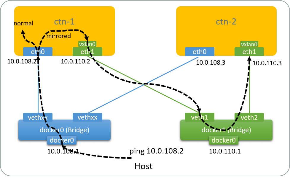
Fig 2.7. Traffic path of the mirror test
2.4 Clean up
Remove filter and qdisc:
$ nsenter -t $NETNS1 -n tc filter del dev eth0 ingress
$ nsenter -t $NETNS1 -n tc qdisc del dev eth0 ingress
Remove network devices:
$ nsenter -t $NETNS1 -n ip link del vxlan0
$ nsenter -t $NETNS2 -n ip link del vxlan0

$ ip link del veth1
$ ip link del veth2
Remove bridge:
$ ip link del docker1
Remove containers:
$ docker rm -f ctn-1
$ docker rm -f ctn-2
3 Remarks
3.1 MTU
Encapsulation will add additional headers to the original packets, so eth1
should have a large MTU than eth0. Otherwise, big packets will not
be mirrored but dropped.
3.2 Filter specific packets
You could choose what type of packets to filter, e.g. ICMP packets, UDP packet, refer to [2, 5] for more examples.
3.3 Other tunneling alternatives
As has been said, VxLAN is only one of the encapsulation formats. You could try other formats, e.g. GRE [2].
3.4 Performance
Software encapsulation/decapsulation takes nontrival amount of CPU resource, but this is beyond the scope of this post.
References
- Wikipedia: Port Mirroring
- Traffic Mirroring with Linux Tc
- An introduction to Linux virtual interfaces: Tunnels
- Introduction to Linux interfaces for virtual networking
- Chapter 9: Queueing Disciplines for Bandwidth Management, Linux Advanced Routing & Traffic Control HOWTO
- Traffic Mirroring with OVS
Appendix: Topology discovery of docker bridge network
This appendix explores how containers connect to bridge docker0 (how the following picture comes):
Fig 2.1. Default network topology of docker containers
First, get the detailed information about network device docker0:
# -d/--details
$ ip -d link show docker0
9: docker0: <BROADCAST,MULTICAST,UP,LOWER_UP> mtu 1500 qdisc noqueue state UP mode DEFAULT group default
    link/ether 02:42:bd:e4:7a:85 brd ff:ff:ff:ff:ff:ff promiscuity 0
    bridge forward_delay 1500 hello_time 200 max_age 2000 ageing_time 30000 stp_state 0 priority 32768
           vlan_filtering 0 vlan_protocol 802.1Q bridge_id 8000.2:42:bd:e4:7a:85 ...
in the above output,
bridgeindicates this is a bridge type device- parameters after
bridge(foward_delay,hello_time, etc) are its configuration parameters
In the same way, get the defailed information about eth0 inside ctn-1:
$ nsenter-ctn ctn-1 -n ip -d link show dev eth0
258: eth0@if259: <BROADCAST,MULTICAST,UP,LOWER_UP> mtu 1500 qdisc noqueue state UP mode DEFAULT group default qlen 1000
    veth addrgenmode eui64 numtxqueues 1 numrxqueues 1 gso_max_size 65536 gso_max_segs 65535
It says,
eth0is one end of aveth pairdevice, with interface ID258; note that this index is unique within the node (instead of the container)- the other end of the veth pair has an interface index
259
Find the device with index 259:
$ ip link | grep 259
259: veth159e062@if258: <BROADCAST,MULTICAST,UP,LOWER_UP> mtu 1500 ...
Then show the device details:
$ ip -d link show veth159e062
259: veth159e062@if258: <BROADCAST,MULTICAST,UP,LOWER_UP> mtu 1500 master docker0 ...
    veth
    bridge_slave state forwarding priority 32 ...
bridge_slavemeans this device is attached to a bridgemaster docker0further gives us the bridge name:docker0
At this point, we know that ctn-1 connects to docker0 with a path
eth0 -> veth159e062 -> docker0.
Repeat the same procedure for ctn-2, we will just get the picture in the above.