Life of a Packet in Cilium: Discovering the Pod-to-Service Traffic Path and BPF Processing Logics
Note: this post also provides a Chinese version, but may update less timely as this one.
- Introduction
- Step 1: POD1
eth0: accessing a Service - Step 2: POD1
lxcdevice: POD1 egress BPF processing - Step 3: NODE1: kernel routing
- Step 4: NODE1 bond/NIC: egress BPF processing
- Step 5: Data center network: routing
- Step 6: NODE2 NIC/bond: ingress BPF processing
- Step 7: POD4: ingress BPF processing
- Step 8: Arrived POD4’s
eth0 - Conclusion
- References
Introduction
Problem faced
Traditional network virtualization schemes mostly base on L2 forwarding (Linux bridge, Netfilter/iptables, OVS, etc) and/or L3 routing. Under these schemes, there is usually a very clear packet traversing path, where you could determine the next hop of a packet with common network tools, and ended with a picture like following [1]:
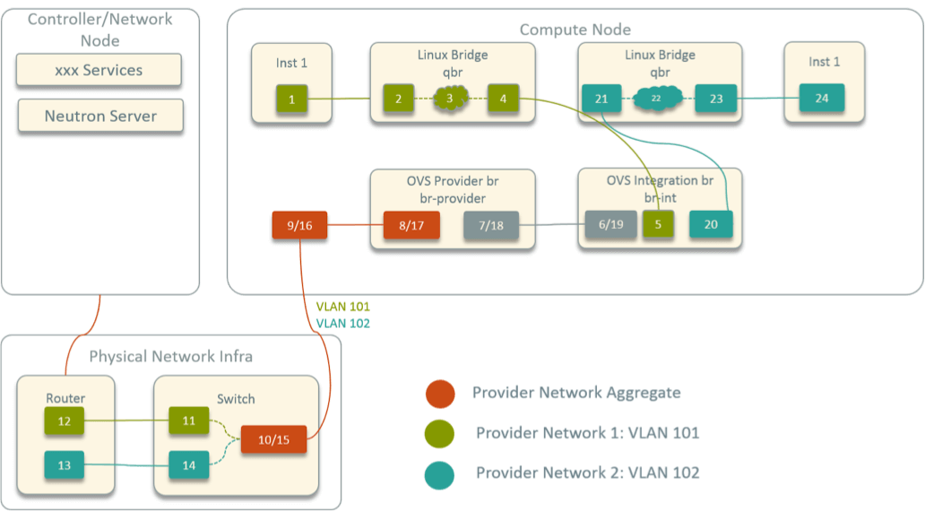
Fig 1. Network topology inside an OpenStack compute node
When network problems are reported, such as one container not reaching another one, you could capture the traffic along the forwarding path, and by combining routing table and ARP table information, most of the time you could quickly locate the problem.
Unfortunately, the topology is no longer that straight forward in Cilium networking solution. For example, below is the network topology inside Cilium-powered nodes with the default installation:
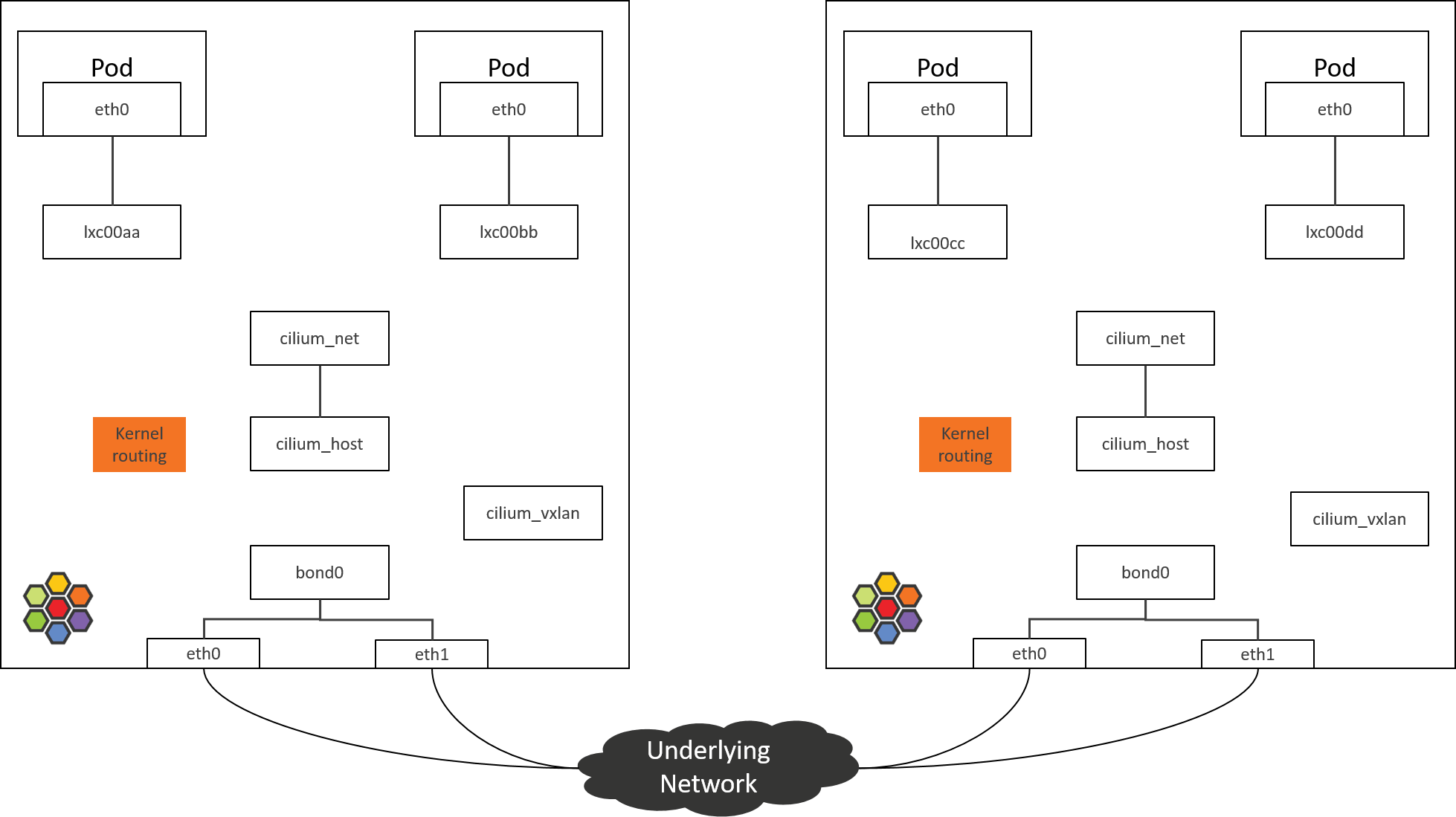
Fig 2. Network topology inside an Cilium-powered k8s node
As can be seen, network devices now seems to be “disconnected from each other”,
there are no bridging devices or normal forwarding/routing rules that connect
them. If capturing the traffic with tcpdump, you may see that the traffic
disappears somewhere, then suddenly spring out in another place. It
confuses people how the traffic is transferred between the devices, and to
the best we could guess is that it is done by BPF.
This might be the biggest headache when you are trouble-shooting in Cilium clusters.
This post intends to alleviate this.
Purpose of this post
In this post, we will explore or discover the detailed packet forwarding path in Cilium with such an example: accesing a ServiceIP from a Pod on a node, where the backend Pods of the Service run on another node.
We will achieve this goal by utilizing some commonly used Linux command line tools, and by analyzing the BPF source code in Cilium. Our final output will be a topology picture like below:
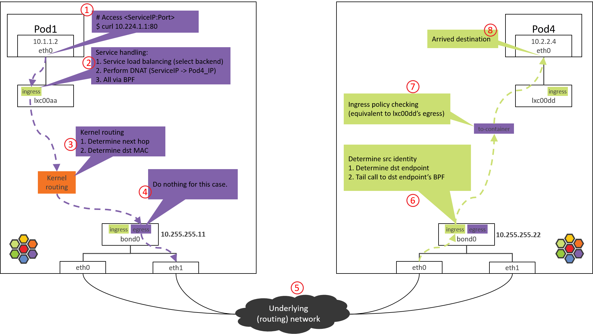
Fig 3. Traffic path of Pod-to-ServiceIP
References [2,3,5] also covered this topic, but they stay at a high-level. We in this post will dig into the code level. We strongly suggest readers to first read [2,3] before continuing.
Environments and configurations
Forwarding path in Cilium varies according to the different cross-host networking solutions you choose, we assume in this post that:
- Cross-host networking solution: direct routing (via BGP [4]).
- Linux kernel
4.19: Cilium/eBPF relies on this for the features we use. - Cilium
1.8.2, with configurations:kube-proxy-replacement=probe(default)enable-ipv4=true(default)datapath-mode=veth(default)
- No network policies (default).
- On each node, there are two NICs and they are bonded, with node IP configured on bond device.
With 2 & 3, all the hooking and modification jobs on the traffic will be
fulfilled by BPF code, thus completely removes Netfilter/iptables dependency,
this is the so-called kube-proxy free mode.
Other aspects
For ease of illustration, we will use a host command nsenter-ctn to
execute commands inside containers. It’s actually a simple wrapper over
nsenter:
(NODE1) $ cat ~/.bashrc
...
function nsenter-ctn () {
    CTN=$1  # container ID or name
    PID=$(sudo docker inspect --format "{{.State.Pid}}" $CTN)
    shift 1 # remove the first argument, shift others to the left
    nsenter -t $PID $@
}
This is equivalent to docker exec <ctn> <command>, for more info, refer to
man nseneter.
Step 1: POD1 eth0: accessing a Service
Following devices are no longer needed in our conditions, so we just omit them in the subsequent pictures:
cilium_net/cilium_host: no longer performs real actions in Kernel4.19+ Cilium1.8(and the community is considering to remove it).cilium_vxlan: responsible for tunnel encap/decap, only appears in tunnel mode.
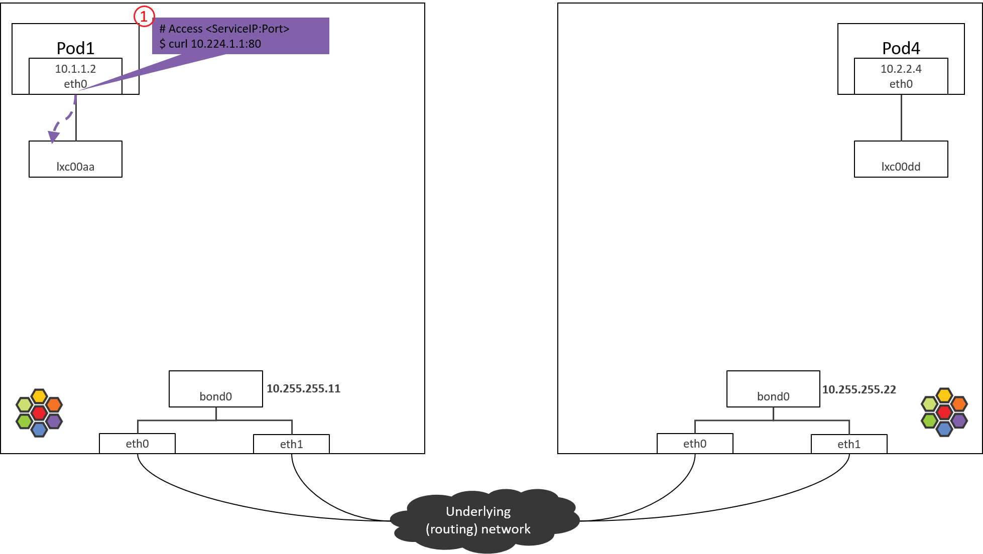
Fig. Step 1.
1.1 Accessing ServiceIP
Start from accessing a ServiceIP from a Pod, such as:
# * -n: execute command in pod's network namespace
# * 10.224.1.1: ServiceIP
(NODE1) $ nsenter-ctn pod1 -n curl 10.224.1.1:80
Packets will be sent out via eth0 of POD1, we can determine that for these
packets,
src_ip=POD1_IPsrc_mac=POD1_MACdst_ip=ServiceIP
These are easy to understand, but how about dst_mac?
1.2 Determine dst_mac: routing side POD1
For determining dst_mac, we need to look at the routing table and ARP table
inside POD1.
First, the routing table:
(NODE1) $ nsenter-ctn pod1 -n route -n
Kernel IP routing table
Destination     Gateway         Genmask         Flags Metric Ref    Use Iface
0.0.0.0         10.1.1.1        0.0.0.0         UG    0      0        0 eth0
10.1.1.1        0.0.0.0         255.255.255.255 UH    0      0        0 eth0
This node manages PodCIDR 10.1.1.0/24, and 10.1.1.1 is the gateway of this
PodCIDR, configured on cilium_host device, you could verify this by executing
ifconfig cilium_host on the node. Cilium agent configures this
automatically on starting.
According to the above routing rules:
- All packets targeted to gateway
10.1.1.1will hit the second rule. - All other packets, hit the first rule (default rule).
As ServiceIP is 10.224.1.1, it will hit the default rule, so the next hop is
gateway 10.1.1.1. Thus, dst_mac should be the MAC corresponding to
IP address 10.1.1.1. This mapping info stores in ARP table.
Now check the ARP table inside POD1:
(NODE1) $ nsenter-ctn pod1 -n arp -n
Address               HWtype  HWaddress           Flags Mask            Iface
10.1.1.1              ether   3e:74:f2:60:ab:9b   C                     eth0
Got the MAC address we are looking for: 3e:74:f2:60:ab:9b. And
now, the packet could be sent out correctly with this MAC as dst_mac.
1.3 Next hop: further digging
If you search the above MAC address on NODE1, you will find that it actually
doesn’t belongs to cilium_host/cilium_net:
(NODE1) $ ifconfig cilium_host
cilium_host: flags=4291<UP,BROADCAST,RUNNING,NOARP,MULTICAST>  mtu 1500
        inet 10.1.1.1  netmask 255.255.255.255  broadcast 0.0.0.0
        ether 3e:7d:6b:32:44:8e  txqueuelen 1000  (Ethernet)
        ...
and,
(NODE1) $ ip link | grep 3e:74:f2:60:ab:9b -B 1
699: lxc00aa@if698: <BROADCAST,MULTICAST,UP,LOWER_UP> mtu 1500 qdisc noqueue
    link/ether 3e:74:f2:60:ab:9b brd ff:ff:ff:ff:ff:ff link-netnsid 4
As the output shows, it is the address of a device named lxc00aa.
The @ symbol indicates that it is one end of a veth pair, with interface
index (ifindex) 699, and its peer end has an ifindex 698.
With this in mind, execute ip link inside POD1:
(NODE1) $ nsenter-ctn pod1 -n ip link
698: eth0@if699: <BROADCAST,MULTICAST,UP,LOWER_UP> mtu 1500 qdisc noqueue
    link/ether 5e:d9:e5:0d:a1:ed brd ff:ff:ff:ff:ff:ff link-netnsid 0
eth0 inside POD1 is just the peer end of lxc00aa.
Now it’s clear: Cilium hijacks ARP table of POD1, forces the next hop to be the peer end (host side) of the veth pair. We will not go further into the design, but just remind you that this is not a Cilium-specific design, there are also other networking solutions that behave so.
Step 2: POD1 lxc device: POD1 egress BPF processing
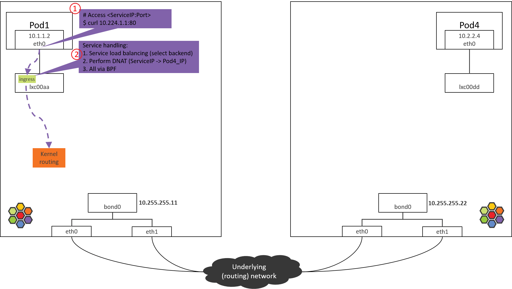
Fig. Step 2.
2.1 Check the loaded BPF program
The packet sent out from eth0 will be received by lxc00aa, so at the
tc ingress hook (rather than the egress hook), it can do filtering
and processing on the packets sent out from POD1.
- POD1’s egress corresponds to lxc’s ingress.
- POD1’s ingress corresponds to lxc’s egress.
Now check the loaded BPF programs at the tc ingress hook:
(NODE1) $ tc filter show dev lxc00aa ingress
filter protocol all pref 1 bpf
filter protocol all pref 1 bpf handle 0x1 bpf_lxc.o:[from-container] direct-action not_in_hw tag 3855f578c6616972
as shown above, there is indeed a BPF program, loaded at section
from-container. The section label from-container is a unique
identifier for this program, we can easily find the program code in Cilium
repository by searching this identifier.
In veth pair mode, you could also use the above tc command to list the loaded BPF programs at
eth0’s ingress/egress hooks andlxc00aa’s egress hooking points, then you will find that there are not any BPF programs at these places.Then the question is: how will Cilium perform ingress processing if there are no corresponding BPF programs? We will reveal this later.
Now let’s see what this BPF program will do.
2.2 from-container BPF Code Analysis
All BPF codes in Cilium lay at the bpf/ folder in Cilium source code
tree. To avoid to be too lengthy, we will only show the call stacks of
each BPF program.
Now let’s see the first one in this post,
__section("from-container")
handle_xgress                                                                   // bpf/bpf_lxc.c
  |-validate_ethertype(skb, &proto)
  |-switch (proto) {
      case ETH_P_IP:
          tail_handle_ipv4                                                     // bpf/bpf_lxc.c
            |-handle_ipv4_from_lxc                                             // bpf/bpf_lxc.c
                |-if dst is k8s Service
                |    lb4_local()
                |      |-ct_create4
                |      |-lb4_lookup_backend
                |      |-lb4_xlate
                |
                |-policy_can_egress4()
                |
                |-if tunnel
                |     encap vxlan
                | else // direct routing, pass to kernel stack (continue normal routing)
                |     ipv4_l3()                       // dec TTL, set src/dst MAC
                |     asm_set_seclabel_identity(skb); // set identity to skb
                |-return TC_ACT_OK;
    }
Main actions:
- Validate the packet (skb), and extract L3 protocol.
- If L3 proto is IPv4, call
tail_handle_ipv4()for further processing. -
tail_handle_ipv4()further callshandle_ipv4_from_lxc(), the latter performs:- Service load balancing: select a proper Pod from backend list, we assume POD4 on NODE2 is selected.
- Create or update connection tracking (CT or conntrack) record.
- Perform DNAT, replace ServiceIP with
POD4_IPfor thedst_ipfield in IP header. - Perform egress network policy checking.
- Perform encapsulation if in tunnel mode, or pass the packet to kernel stack if in direct routing mode., we will see the latter one.
Before passing to kernel stack, it calls ipv4_l3(), which will set TTL、
MAC addresses, etc:
int
ipv4_l3(struct __ctx_buff *ctx, int l3_off, __u8 *smac, __u8 *dmac, struct iphdr *ip4)
{
    ipv4_dec_ttl(ctx, l3_off, ip4));
    if (smac)
       eth_store_saddr(ctx, smac, 0);
    eth_store_daddr(ctx, dmac, 0);

    return CTX_ACT_OK;
}
At last, BPF program returns TC_ACK_OK to the kernel, then this packet
enters kernel stack for further processing.
Step 3: NODE1: kernel routing
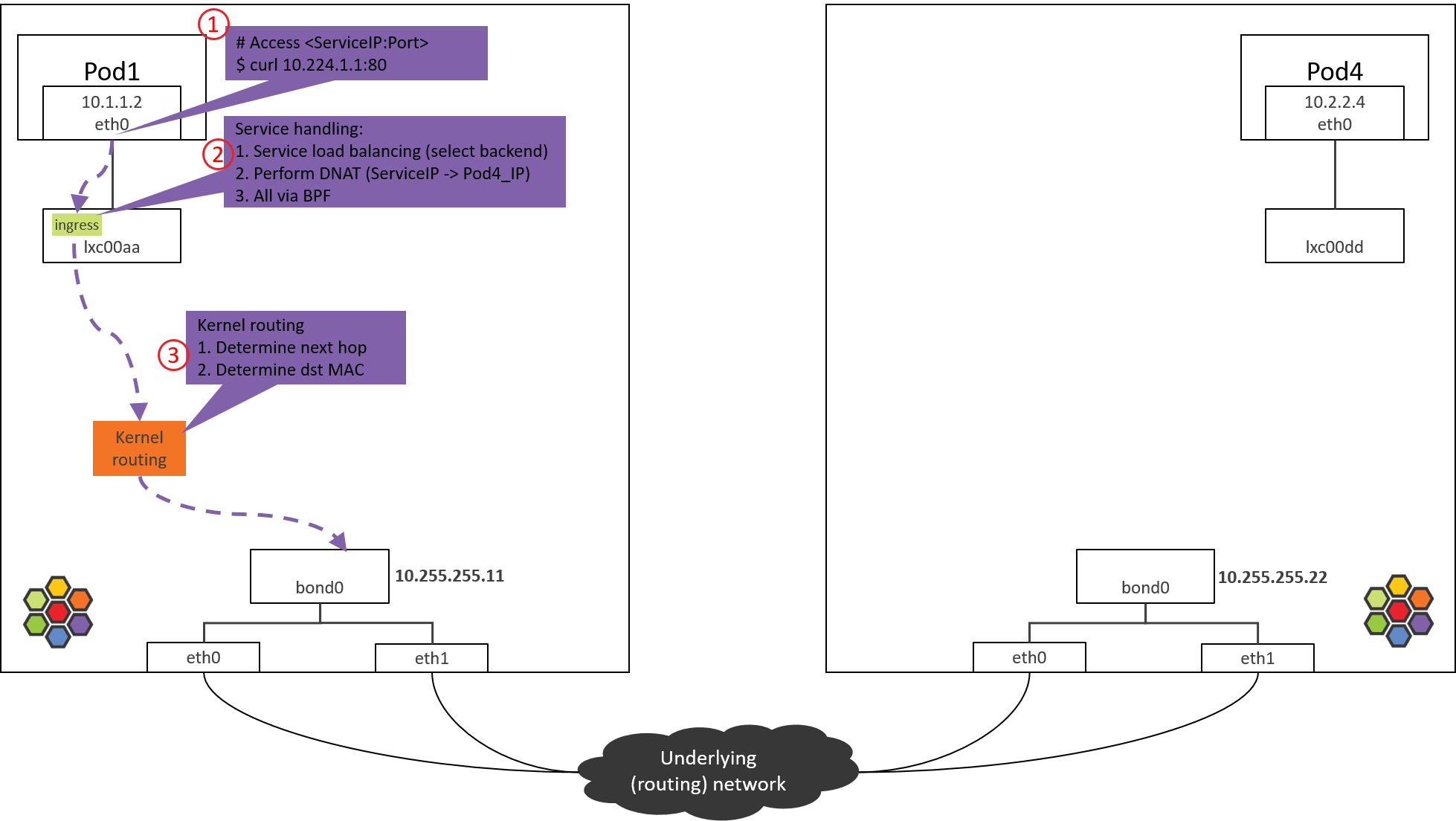
Fig. Step 3.
After the from-container BPF program finishes processing in Step 2, dst_ip
now has been the real Pod IP (POD4_IP).
Now the kernel will perform routing for this packet. Kernel acts as a software
router now: it looks up routing table with dst_ip, then determines the next
hop.
Kernel routing table of NODE1:
(NODE1) $ route -n
Kernel IP routing table
Destination     Gateway         Genmask         Flags Metric Ref    Use Iface
0.0.0.0         10.255.255.1    0.0.0.0         UG    0      0        0 bond0
10.1.1.0        10.1.1.1        255.255.255.0   UG    0      0        0 cilium_host
10.1.1.1        0.0.0.0         255.255.255.255 UH    0      0        0 cilium_host
According to above rules, all packets with dst_ip not fall into PodCIDR
10.1.1.0/24 will hit the default rule (first rule in the above), and will be
sent out via bond0 device:
For more information on kernel routing subsystem (L3 routing), neighbor subsystem (L2 forwarding), I recommend the thick book Understanding Linux Network Internals. The book uses an older kernel, but the general routing & forwarding design still validates.
So in the next the packet will arrive at bond0 device.
Nodes in this post are shipped with two NICs, bonded into
bond0. For nodes with only one NIC, e.g. eth0, and the host IP is configured on this NIC, the packet will arrive eth0 instead of bond0 here. The devices which hold host IPs are called “native devicess” in Cilium, you may encounter them when reading the doc or code.
Step 4: NODE1 bond/NIC: egress BPF processing
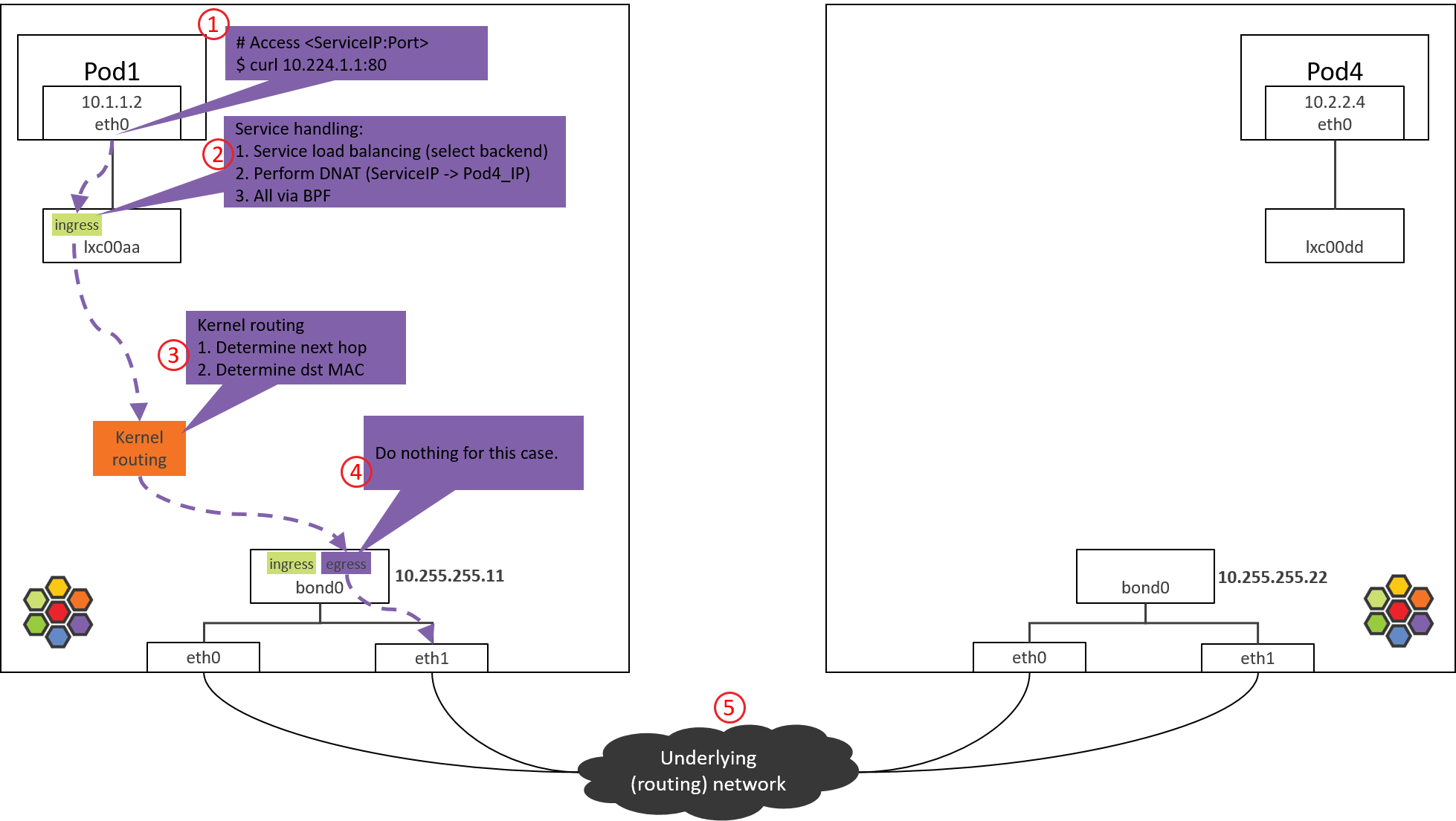
Fig. Step 4.
4.1 Check the loaded BPF program
Check the BPF program loaded at the egress direction, this is the last tc BPF hook before the packet leaves this host:
(NODE1) $ tc filter show dev bond0 egress
filter protocol all pref 1 bpf
filter protocol all pref 1 bpf handle 0x1 bpf_netdev_bond0.o:[to-netdev] direct-action not_in_hw tag b536a7e2744a4cdb
Next, let’s see the code implementation.
4.2 to-netdev BPF Code Analysis
Call stack,
__section("to-netdev")
to_netdev
  |-policy_clear_mark
  |-src_id = resolve_srcid_ipv4
  |   |-lookup_ip4_remote_endpoint
  |       |-ipcache_lookup4
  |-ipv4_host_policy_egress(src_id)
      |-policy_can_egress4
      |-ret = ct_lookup4()
      |-switch (ret) {
          case CT_NEW        : ct_create4(); break;
          case CT_ESTABLISHED:
          case CT_RELATED    :
          case CT_REPLY      :               break;
          default            : ret = DROP;   break;
        }
        return ret;
Roughly say, for our case, this BPF actually does nothing important, it just
returns TC_ACK_OK to let the packet go.
BPF programs on native devices are mainly used for North-South traffic processing, namely, the external (in & out k8s cluster) traffic [3]. This includes,
- Traffic of LoadBalancer Services
- Traffic of ClusterIP Services with externalIPs
- Traffic of NodePort Services
In the next, kernel will lookup routing table and ARP table, and encap the L2 header for the packet.
4.3 Determine src_mac and dst_mac
Same as 1.2, we omit analysis process, just give the result:
$ route -n
Kernel IP routing table
Destination     Gateway         Genmask         Flags Metric Ref    Use Iface
0.0.0.0         10.255.255.1    0.0.0.0         UG    0      0        0 bond0
10.1.1.0        10.1.1.1        255.255.255.0   UG    0      0        0 cilium_host
10.1.1.1        0.0.0.0         255.255.255.255 UH    0      0        0 cilium_host

$ arp -n
Address                  HWtype  HWaddress           Flags Mask            Iface
10.255.255.1             ether   00:00:5e:00:01:0c   C                     bond0
This packet will hit the default routing rule on the kernel routing table, so it determines,
bond0’s MAC to besrc_mac: MAC addresses are only meaningful inside a L2 network, the host and Pod are in different L2 networks (Cilium manages a distinct CIDR/network), so the host will set its own MAC address assrc_macwhen forwarding this packet.- The MAC of host’s gateway (
10.255.255.1) to bedst_mac: next hop is host’s gateway.
Then, the packet will be sent to the underlying data center network via bond0 (and physical NICS).
For validation, you could capture the packets with
tcpdumponbond0and NICs, specify-eto print MAC addresses.
Step 5: Data center network: routing
Fig. Step 5.
Data center network routes packets based on dst_ip.
As NODE2 has already announced that PodCIDR2 via BGP, and POD4_IP falls into
PodCIDR2, so routers will pass this packet to NODE2.
Network Virtualization: cross-host networking.
From network layer’s perspective, there are two kinds of cross-host networking schemes:
- L2/LL2 (Large L2): run a software switch or software bridge inside each node, typical: OpenStack Neutron+OVS [1].
- L3: run a software router inside each node (actually kernel itself is the router), each node is a layer 3 node, typical: Cilium+BGP [4].
One big difference when trouble shooting:
- In L2/LL2 network, src_mac stays unchanged during the entire path, so receiver sees the same src_mac as sender does; L2 forwarding only changes dst_mac;
- In L3 network, both src_mac and dst_mac will be changed.
Understanding this is important when you capture packets.
Step 6: NODE2 NIC/bond: ingress BPF processing
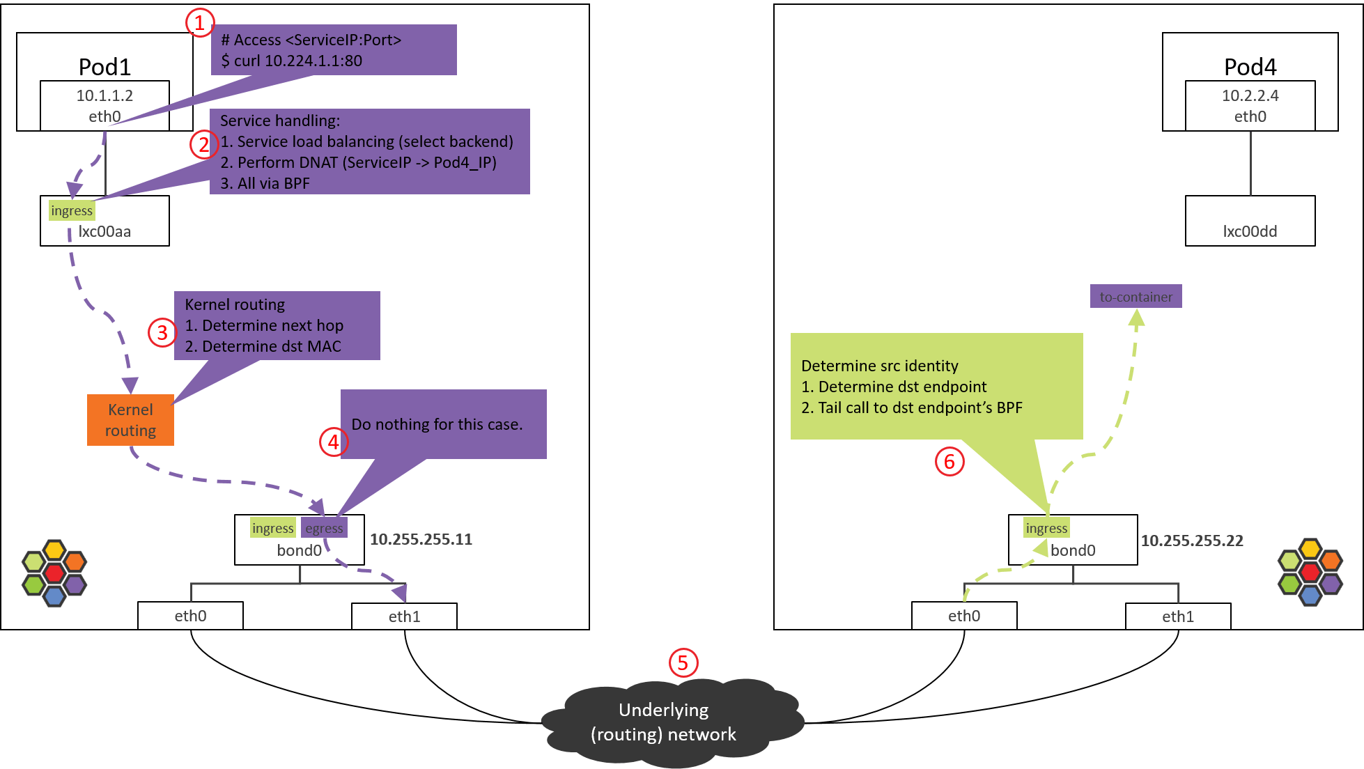
Fig. Step 6.
Take Intel 10G ixgbe NIC as example, the calling stack starting from driver,
// kernel source tree, 4.19

ixgbe_poll
 |-ixgbe_clean_rx_irq
    |-if support XDP offload
    |    skb = ixgbe_run_xdp()
    |-skb = ixgbe_construct_skb()
    |-ixgbe_rx_skb
       |-napi_gro_receive
          |-napi_skb_finish(dev_gro_receive(skb))
             |-netif_receive_skb_internal
                |-if generic XDP
                |  |-if do_xdp_generic() != XDP_PASS
                |       return NET_RX_DROP
                |-__netif_receive_skb(skb)
                   |-__netif_receive_skb_one_core
                      |-__netif_receive_skb_core(&pt_prev)
                         |-for tap in taps:
                         |   deliver_skb
                         |-sch_handle_ingress                     // net/core/dev.c
                            |-tcf_classify                        // net/sched/cls_api.c
                               |-for tp in tps:
                                   tp->classify
                                       |-cls_bpf_classify         // net/sched/cls_bpf.c
Main steps:
- NIC received a packet.
- Execute XDP programs if there are XDP programs and NIC supports XDP offload (not our case here).
- Create
skb. - Do GRO, assemble fragemented packets.
- Generic XDP processing: if NIC doesn’t support XDP offload, then XDP programs will be delayed to execute here from step 2.
- Tap processing (not our case here).
- TC ingress processing, execute TC programs, and tc BPF program is one kind.
6.1 Check the loaded BPF program
Check the BPF program loaded at tc ingress hook:
$ tc filter show dev bond0 ingress
filter protocol all pref 1 bpf
filter protocol all pref 1 bpf handle 0x1 bpf_netdev_bond0.o:[from-netdev] direct-action not_in_hw tag 75f509de02b2dfaf
This piece of BPF will process the traffic coming into bond0 via physical NICs.
6.2 from-netdev BPF Code Analysis
Call stack:
__section("from-netdev")
from_netdev
  |-handle_netdev
      |-validate_ethertype
      |-do_netdev
          |-identity = resolve_srcid_ipv4()                // extract src identity from ctx (skb)
          |-ctx_store_meta(CB_SRC_IDENTITY, identity)      // save identity to ctx->cb[CB_SRC_IDENTITY]
          |-ep_tail_call(ctx, CILIUM_CALL_IPV4_FROM_LXC)   // tail call
                               |
 |------------------------------
 |
__section_tail(CILIUM_MAP_CALLS, CILIUM_CALL_IPV4_FROM_LXC)
tail_handle_ipv4_from_netdev
  |-tail_handle_ipv4
      |-handle_ipv4
          |-ep = lookup_ip4_endpoint()
          |-ipv4_local_delivery(ctx, ep)
              |-tail_call_dynamic(ctx, &POLICY_CALL_MAP, ep->lxc_id);
Main logics:
-
Call
handle_netdev()to process the packets that will enter Cilium-managed network from host, specific things including,- Extract identity of this packet (Cilium relies on identity for policy enforcement), and save it to packet’s metadata.
- In direct routing mode, lookup identity from ipcache (ipcache syncs itself with cilium’s kvstore).
- In tunnel mode, identity is encapsulated in VxLAN header, so no need to lookup ipcache.
- Tail call to
tail_handle_ipv4_from_netdev().
- Extract identity of this packet (Cilium relies on identity for policy enforcement), and save it to packet’s metadata.
-
tail_handle_ipv4_from_netdev()callstail_handle_ipv4(), the latter further callshandle_ipv4().handle_ipv4()performs:- Determine the endpoint (POD4) that
dst_iprelates to. - Call
ipv4_local_delivery(), this method will tail call to endpoint’s BPF for Pod egress processing.
- Determine the endpoint (POD4) that
Step 7: POD4: ingress BPF processing
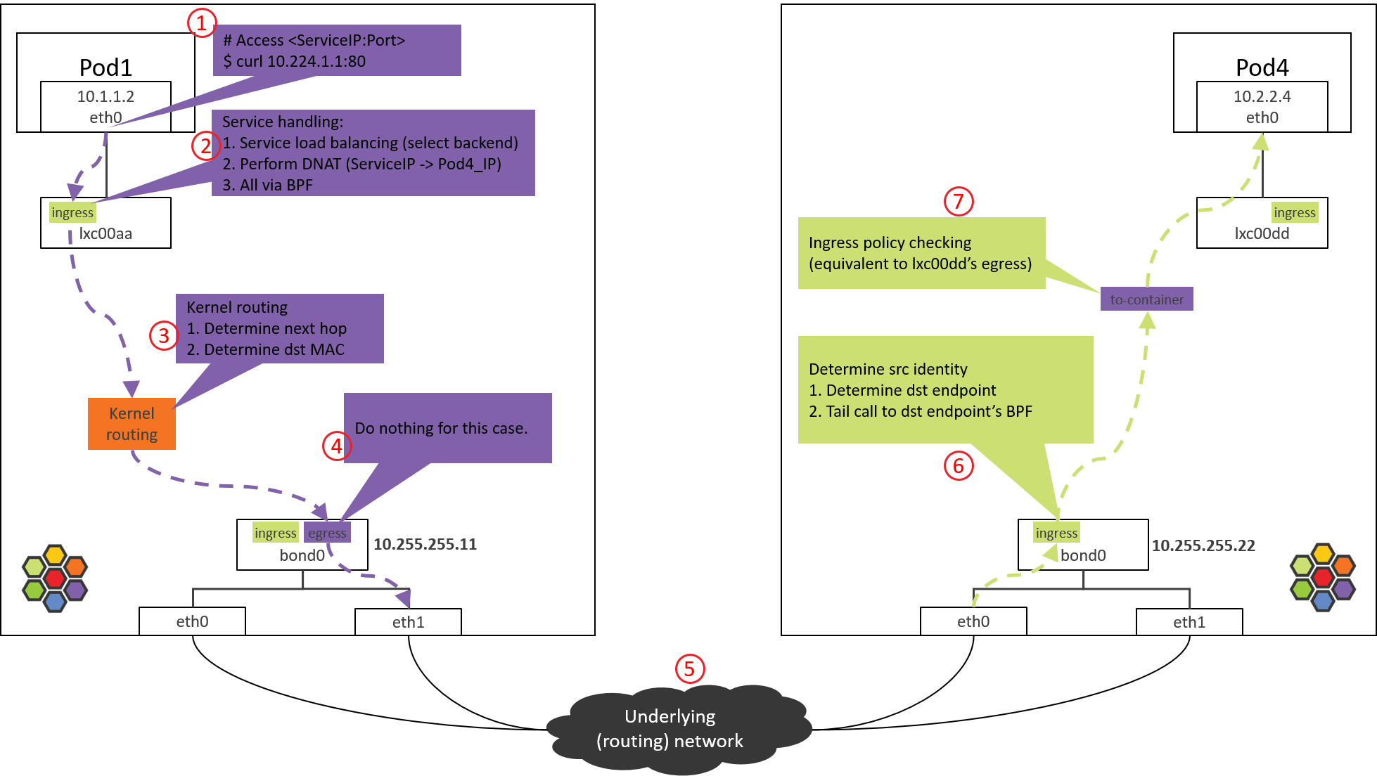
Fig. Step 7.
7.1 Check the loaded BPF program
Just as previous sections, let’s look at the egress hook of POD4’s lxc00dd
(this corresponding to POD4’s ingress),
(NODE2) $ tc filter show dev lxc00dd egress
Not any loaded BPF programs, why?
It’s because in Cilium’s design (performance optimization), the Pod ingress
program is not triggered to execute (normal way), but directly via tail call
(short-cut) from bond0’s BPF:
tail_call_dynamic(ctx, &POLICY_CALL_MAP, ep->lxc_id);
So the ingress BPF needs not to be loaded to lxc00dd, and this also answers
the question we asked in section 2.1.
7.2 to-container BPF Code Analysis
The tail-call calls to to-container BPF. Call stack:
__section("to-container")
handle_to_container                                            //    bpf/bpf_lxc.c
  |-inherit_identity_from_host(skb, &identity)                 // -> bpf/lib/identity.h
  |-tail_ipv4_to_endpoint                                      //    bpf/bpf_lxc.c
      |-ipv4_policy                                            //    bpf/bpf_lxc.c
          |-policy_can_access_ingress                          //    bpf/lib/policy.h
              |-__policy_can_access                            //    bpf/lib/policy.h
                  |-if p = map_lookup_elem(l3l4_key); p     // L3+L4 policy
                  |    return TC_ACK_OK
                  |-if p = map_lookup_elem(l4only_key); p   // L4-Only policy
                  |    return TC_ACK_OK
                  |-if p = map_lookup_elem(l3only_key); p   // L3-Only policy
                  |    return TC_ACK_OK
                  |-if p = map_lookup_elem(allowall_key); p // Allow-all policy
                  |    return TC_ACK_OK
                  |-return DROP_POLICY;                     // DROP
Things done by this piece of BPF:
- Extract src identity of this packet, actually this info is already in packet’s metadata.
- Call
tail_ipv4_to_endpoint(), which will further callipv4_policy(), the latter performs POD4’s ingress network policy checking.
If the packet is not denied by network policy, it will be forwarded to
lxc00dd’s peer end, namely, POD4’s virtual NIC eth0.
Step 8: Arrived POD4’s eth0
Fig. Step 8.
On arriving eth0 of POD4, it could be processed by upper layers.
Conclusion
This post explored the end-to-end traversing path of Pod-to-Service traffic, and also analyzed the BPF logics in each tc BPF hooking point.
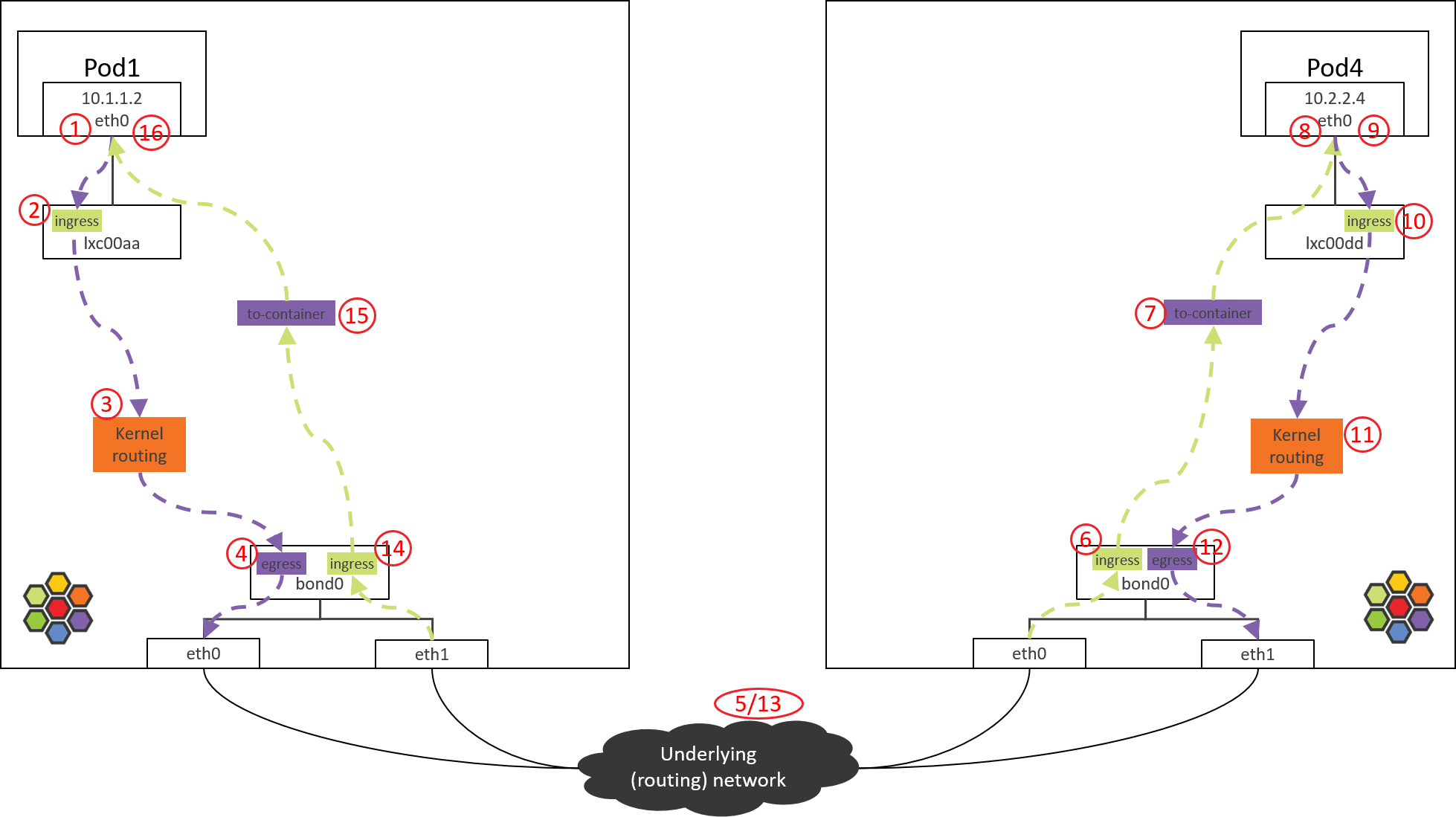
For space limit, we only showed the request path (POD1 to POD4). But, the reply path (POD4 to POD1) is quite similar, and we leave this to the readers who are interested.
At last, there is one important thing that needs to be noted: do not make any performance assumptions by comparing the number of hops between Cilium/eBPF and OpenStack/OVS topologies as shown in this post, as “hop” in Cilium/eBPF is a different concept in this post, mainly used for illustrating the processing steps, and it is not comparable with a traditional “hop”. For example, Step 6 to Step 7 is just a function call, it costs almost nothing in terms of forwarding benchmarks.
References
- Ctrip Network Architecture Evolution in the Cloud Computing Era (2019)
- Understanding (and Troubleshooting) the eBPF Datapath in Cilium
- eBPF and Kubernetes: Little Helper Minions for Scaling Microservices
- Using BIRD to run BGP — Cilium 1.8.3 documentation
- Cilium Network Topology and Traffic Path on AWS